Vectors in 2D and 3D
By the end of this session, you will be able to:
- Plot coordinates and calculate distances/equations of spheres in a 3D rectangular coordinate system.
- Represent vectors in component form and unit-vector notation in 2D and 3D, and calculate their magnitudes and directions.
- Perform vector operations (addition, subtraction, scalar multiplication, unit vectors) and apply them to model physical systems in static equilibrium.
📅 Micro-Lecture
1. 3D Coordinates & Spatial Geometry
- Mathematical Foundation: In the three-dimensional rectangular coordinate system, points are represented as ordered triples (x,y,z). The distance between two points P1(x1,y1,z1) and P2(x2,y2,z2) is d=(x2−x1)2+(y2−y1)2+(z2−z1)2. A sphere centered at (h,k,l) with radius r is described by the equation (x−h)2+(y−k)2+(z−l)2=r2.
- Engineering Context: Necessary for mapping physical assets in 3D space, coordinate transformations in robotics, modeling spherical blast ranges, and structural piping designs.
2. Vectors and Unit Vector Notation
- Mathematical Foundation: A vector v represents a directed line segment with component form ⟨vx,vy,vz⟩ or standard unit vector form vxi^+vyj^+vzk^. The magnitude is ∣v∣=vx2+vy2+vz2. A unit vector in the direction of v is U^v=∣v∣v, which has a magnitude of 1.
- Engineering Context: Used to define directional loads on joints in CAD modeling, velocity fields in aerodynamics, and electric fields in power systems.
3. Vector Arithmetic & Static Equilibrium
- Mathematical Foundation: Vector addition u+v and scalar multiplication cv are performed component-wise. Under static equilibrium conditions, the net external force vector acting on a point-mass is zero: ∑F=0, which requires the horizontal and vertical components to independently sum to zero.
- Engineering Context: Crucial for calculating tension loads in support cables, resolving wind loads on structures, and structural analysis of crane supports.
Skill Block 1
Real-Life Engineering Applications
3D Coordinate Mapping (Computer Science)
In robotic systems and autonomous navigation, depth cameras (like RGB-D sensors) represent the surroundings as a 3D point cloud. A robot arm is situated at the origin (0,0,0), and its software needs to calculate distances between detected objects to prevent collisions.
A depth sensor detects a cylindrical obstacle with a safety envelope modeled as a sphere centered at C(3,−4,2) meters with a radius of r=1.5 meters. A point obstacle is detected at P(4,−2.5,3) meters.
- Find the distance between the robot arm at the origin O(0,0,0) and the center of the spherical safety envelope C.
- Determine the standard equation of the spherical safety envelope.
- Calculate the distance from the point obstacle P to the center of the safety envelope C. Determine if the point obstacle has breached the safety envelope (i.e., is it inside the sphere?).
& Real-Life Application: Robotic collision-avoidance algorithms use these simple geometric checks in real time. By comparing distance vectors between spatial coordinates and spherical safety envelopes, robots can instantly halt or reroute their paths when a breach is detected, avoiding mechanical damage or injury.
💡 Show Worked Derivation
In robotic systems and autonomous navigation, depth cameras (like RGB-D sensors) represent the surroundings as a 3D point cloud. A robot arm is situated at the origin (0,0,0), and its software needs to calculate distances between detected objects to prevent collisions.
A depth sensor detects a cylindrical obstacle with a safety envelope modeled as a sphere centered at C(3,−4,2) meters with a radius of r=1.5 meters. A point obstacle is detected at P(4,−2.5,3) meters.
- Find the distance between the robot arm at the origin O(0,0,0) and the center of the spherical safety envelope C.
- Determine the standard equation of the spherical safety envelope.
- Calculate the distance from the point obstacle P to the center of the safety envelope C. Determine if the point obstacle has breached the safety envelope (i.e., is it inside the sphere?).
Step-by-Step Solution:
Find the Distance from the Origin to C: Using the 3D distance formula between O(0,0,0) and C(3,−4,2):
dOC=(3−0)2+(−4−0)2+(2−0)2=32+(−4)2+22dOC=9+16+4=29≈5.39 metersDetermine the Equation of the Sphere: The standard equation of a sphere is (x−h)2+(y−k)2+(z−l)2=r2. Substituting the center (h,k,l)=(3,−4,2) and radius r=1.5:
(x−3)2+(y+4)2+(z−2)2=(1.5)2(x−3)2+(y+4)2+(z−2)2=2.25Check if the Safety Envelope is Breached: Calculate the distance from the point obstacle P(4,−2.5,3) to the center C(3,−4,2):
dPC=(4−3)2+(−2.5−(−4))2+(3−2)2dPC=12+(1.5)2+12=1+2.25+1=4.25≈2.06 metersCompare the distance dPC to the radius r: Since dPC≈2.06 m>1.5 m, the point obstacle is outside the safety envelope. The safety envelope has not been breached.
3D Rectangular Coordinates, Distance, and Spheres
General Overview
Skill Block 1 introduces the three-dimensional Cartesian coordinate system, plotting points using the right-hand rule, computing distances in 3D, and algebraic equations of spheres.
Conceptual Framework
- Right-Hand Rule: Determines the direction of the positive z-axis. When you point your right hand's index finger along the positive x-axis and curl your fingers toward the positive y-axis, your thumb points along the positive z-axis.
- 3D Coordinates: Points are represented as (x,y,z).
- Distance in 3D: Measures the straight-line distance between two points in three dimensions.
- Spheres in 3D: A sphere is defined as the set of all points (x,y,z) equidistant from a center (h,k,l).
- Completing the Square: An algebraic technique used to rewrite quadratic expressions into factored squared forms, crucial for identifying standard equations of spheres.
Key Equations & Structural Rules
- 3D Distance: d=(x2−x1)2+(y2−y1)2+(z2−z1)2
- Standard Form of a Sphere: (x−h)2+(y−k)2+(z−l)2=r2
Worked Example A: Distance in 3D
Calculate the distance between the two points P=(5,−2,−1) and Q=(−2,4,−6).
💡 Reveal Worked Solution
- Identify Coordinates: Let P=(x1,y1,z1)=(5,−2,−1) and Q=(x2,y2,z2)=(−2,4,−6).
- Apply Distance Formula:
d=(−2−5)2+(4−(−2))2+(−6−(−1))2
- Simplify:
d=(−7)2+62+(−5)2=49+36+25=110≈10.49
Worked Example B: Equation of a Sphere
Find the standard equation of the sphere centered at (3,−4,2) with a radius of 6.
💡 Reveal Worked Solution
- Identify the Center and Radius: (h,k,l)=(3,−4,2) and r=6.
- Substitute into standard form:
(x−3)2+(y−(−4))2+(z−2)2=62
- Simplify:
(x−3)2+(y+4)2+(z−2)2=36
Worked Example C: Center and Radius of a Sphere
Find the center and radius of the sphere defined by the equation x2+y2+z2−6x+8y−2z−10=0.
💡 Reveal Worked Solution
- Group Variable Terms:
(x2−6x)+(y2+8y)+(z2−2z)=10
- Complete the Square for Each Variable:
(Note: Refer to Completing the Square for a detailed refresher on this algebraic technique.)
- For x: add (2−6)2=9
- For y: add (28)2=16
- For z: add (2−2)2=1
Add these values to both sides of the equation:
(x2−6x+9)+(y2+8y+16)+(z2−2z+1)=10+9+16+1
- Write in Standard Form:
(x−3)2+(y+4)2+(z−1)2=36The center is (3,−4,1) and the radius is r=36=6.
Practice Problem 1: Concept & Reading Check
Open this Skill Block on the Memex to locate the information needed to answer the following:
- (a) Under the Conceptual Framework section, describe the Right-Hand Rule and how it determines the positive z-axis.
- (b) Look at the Key Equations & Structural Rules section. What is the standard form equation of a sphere with center (h,k,l) and radius r?
- (c) Trace Worked Example C. Why is the algebraic technique "Completing the Square" used to rewrite the sphere's equation? What values were added to both sides of the equation?
Refer to the Conceptual Framework section (under Right-Hand Rule and Spheres) and the solution to Worked Example C of this Skill Block on the Memex.
Answer: * (a) Curl the fingers of your right hand from the positive x-axis to the positive y-axis; your thumb points in the direction of the positive z-axis.
- (b) (x−h)2+(y−k)2+(z−l)2=r2.
- (c) It is used to group variable terms into perfect square binomials. We added 9 (for x), 16 (for y), and 1 (for z) to both sides.
Step-by-Step Execution
- (a) As outlined in the Conceptual Framework section, the Right-Hand Rule establishes the 3D coordinate orientation. Pointing your right index finger along positive x and curling your fingers to positive y leaves your thumb pointing along the positive z-axis.
- (b) According to the Key Equations & Structural Rules section, the standard equation of a sphere is (x−h)2+(y−k)2+(z−l)2=r2, where (h,k,l) is the center coordinate and r is the radius.
- (c) Tracing Worked Example C, the given equation is x2+y2+z2−6x+8y−2z−10=0. Completing the square groups the quadratic and linear terms for each variable to rewrite them in standard squared form. To balance the equation, we add (−6/2)2=9 for x, (8/2)2=16 for y, and (−2/2)2=1 for z to both sides, transforming the constants on the right side to 10+9+16+1=36.
Practice Problem 2
Label the axes in the coordinate system below according to the right-hand rule, and plot the points A=(5,−4,0), B=(0,3,0), and C=(1,3,2).
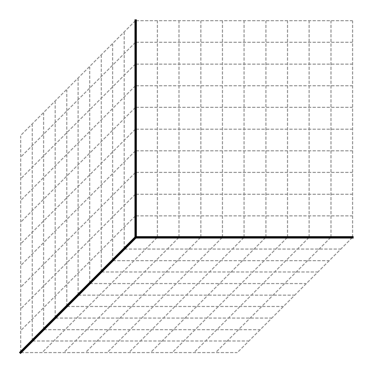
Start by labeling the horizontal right axis as y, the vertical axis as z, and the axis pointing forward/left as x. To plot, move along the x-axis first, then parallel to the y-axis, then parallel to the z-axis.
Answer: Point A lies on the xy-plane at (5,−4,0), point B lies on the y-axis at (0,3,0), and point C lies at (1,3,2) in the first octant.
Step-by-Step Execution
- Establish the Axes: Following the standard convention for the right-hand rule:
- The x-axis points diagonally forward and to the left.
- The y-axis points horizontally to the right.
- The z-axis points vertically upward.
- Plot Point A (5, -4, 0):
- Move 5 units forward along the positive x-axis.
- Move 4 units parallel to the negative y-axis (to the left).
- Since the z-coordinate is 0, the point lies directly on the xy-plane.
- Plot Point B (0, 3, 0):
- The x- and z-coordinates are 0.
- Move 3 units to the right along the positive y-axis.
- Plot Point C (1, 3, 2):
- Move 1 unit forward along the positive x-axis.
- Move 3 units to the right parallel to the positive y-axis.
- Move 2 units upward parallel to the positive z-axis.
Practice Problem 3
Determine if the equation x2+y2+z2+8x−4y+12z+47=0 represents a sphere. If it does, find its center and radius.
Group the variables and complete the square for each one. Remember to add the same constants to both sides of the equation.
Answer: Center: (−4,2,−6), Radius: r=3
Step-by-Step Execution
- Group terms:
(x2+8x)+(y2−4y)+(z2+12z)=−47
- Complete the square:
(Apply the Completing the Square technique to each variable):
- For x: add (28)2=16
- For y: add (2−4)2=4
- For z: add (212)2=36
Add these to both sides:
(x2+8x+16)+(y2−4y+4)+(z2+12z+36)=−47+16+4+36
- Simplify:
(x+4)2+(y−2)2+(z+6)2=9Since the right side is positive (9>0), it is a sphere. Center: (−4,2,−6) Radius: r=9=3
📅 Regroup 1
- Review coordinate axes orientations and right-hand rule.
- Address common errors in completing the square (e.g. sign errors and forgetting to add terms to both sides).
Skill Block 2
Real-Life Engineering Applications
Cable Displacement Vectors (Construction Management)
In structural construction, cable lines are installed to anchor tall towers. Construction managers must determine the length and spatial direction of the cables from the coordinates of the anchor points to ensure proper procurement and site layout.
A support tower has its base at the origin and rises vertically along the z-axis. A cable is to be connected from a point P(0,0,45) meters high on the tower to a ground anchor situated at Q(15,−20,0) meters.
- Find the displacement vector PQ representing the cable in component form.
- Find the total length of the cable required (the magnitude of the vector).
- Find the unit vector in the direction of the cable.
& Real-Life Application: Calculating displacement vectors and magnitudes allows construction managers to order the correct length of steel cables. The unit vector represents the direction of the tension force that the cable will exert on both the tower and the ground anchor, which is essential for structural stability calculations.
💡 Show Worked Derivation
In structural construction, cable lines are installed to anchor tall towers. Construction managers must determine the length and spatial direction of the cables from the coordinates of the anchor points to ensure proper procurement and site layout.
A support tower has its base at the origin and rises vertically along the z-axis. A cable is to be connected from a point P(0,0,45) meters high on the tower to a ground anchor situated at Q(15,−20,0) meters.
- Find the displacement vector PQ representing the cable in component form.
- Find the total length of the cable required (the magnitude of the vector).
- Find the unit vector in the direction of the cable.
Step-by-Step Solution:
Find the Displacement Vector PQ: The displacement vector is determined by subtracting the coordinates of the initial point P(0,0,45) from the terminal point Q(15,−20,0):
PQ=⟨15−0,−20−0,0−45⟩=⟨15,−20,−45⟩ metersFind the Cable Length (Magnitude): The length of the cable is the magnitude of the displacement vector:
∣PQ∣=152+(−20)2+(−45)2=225+400+2025=2650∣PQ∣=5106≈51.48 metersFind the Unit Vector (U^): Divide the displacement vector by its magnitude:
U^=∣PQ∣PQ=5106⟨15,−20,−45⟩=⟨1063,−1064,−1069⟩Evaluating the components:U^≈⟨0.291,−0.388,−0.874⟩
Vectors and Vector Notation in 2D and 3D
General Overview
Skill Block 2 defines vectors algebraically in component form and unit-vector notation, and explains how to compute their magnitude and direct them as unit vectors.
Conceptual Framework
- Vectors: Direct mathematical representations of quantities with magnitude and direction.
- Component Form vs. Unit Vector Form: ⟨vx,vy,vz⟩ is equivalent to vxi^+vyj^+vzk^.
- Displacement Vector: Calculated by subtracting the coordinates of the initial point from the terminal point.
- Magnitude: The geometric length of a vector.
- Unit Vector: A scaled version of the vector with a magnitude of 1.
Key Equations & Structural Rules
- Displacement Vector: PQ=⟨xQ−xP,yQ−yP,zQ−zP⟩
- Magnitude: ∣v∣=vx2+vy2+vz2
- Unit Vector: U^v=∣v∣v
Worked Example A: Vector Components and Magnitude
Given the points P1=(2,3) and P2=(4,4), find the vector P starting at P1 and ending at P2 in component form and calculate its magnitude.
💡 Reveal Worked Solution
- Find components:
Px=4−2=2Py=4−3=1Component form: P=⟨2,1⟩ (or unit vector form: P=2i^+1j^).
- Calculate magnitude:
∣∣P∣∣=Px2+Py2=22+12=5
Worked Example B: 3D Vector Representation
A cable exerts a force of magnitude 580 N along a line pointing from the origin to the point (250,100,500) in millimeters. Write the force vector in component form.
💡 Reveal Worked Solution
- Find the direction vector: Let v=⟨250,100,500⟩.
- Compute magnitude of direction vector:
∣v∣=2502+1002+5002=62500+10000+250000=322500≈567.89
- Find the unit vector:
U^v=∣v∣v≈⟨0.4402,0.1761,0.8805⟩
- Scale unit vector by force magnitude:
F=580⋅U^v≈⟨255.33,102.13,510.68⟩ N
Worked Example C: Components from Angle
A vector V has magnitude 7 and makes a 30∘ angle with the positive x-axis. Find its horizontal and vertical components.
💡 Reveal Worked Solution
- Apply trigonometric formulas:
Vx=∣V∣cos(30∘)Vy=∣V∣sin(30∘)
- Evaluate components:
Vx=7⋅23=273≈6.06Vy=7⋅21=3.5Component form: V=⟨273,27⟩.
Practice Problem 4: Concept & Reading Check
Open this Skill Block on the Memex to locate the information needed to answer the following:
- (a) Under the Conceptual Framework section, what is the difference between component form and unit-vector notation for representing a vector in 3D?
- (b) According to the Key Equations & Structural Rules section, what is the formula for calculating a displacement vector PQ from points P and Q?
- (c) Trace Worked Example B. Explain why we calculate a unit vector U^v first before scaling it by the force magnitude of 580 N.
Refer to the Conceptual Framework (under Vectors and standard notations), the Key Equations & Structural Rules (under displacement vectors), and the solution to Worked Example B of this Skill Block on the Memex.
Answer: * (a) Component form uses angle brackets (⟨vx,vy,vz⟩), whereas unit-vector notation uses standard unit coordinate vectors (vxi^+vyj^+vzk^).
- (b) PQ=⟨xQ−xP,yQ−yP,zQ−zP⟩.
- (c) A unit vector represents pure direction with a magnitude of 1. Multiplying this unit vector by the scalar force (580 N) ensures the final force vector points in the correct direction and has precisely the desired magnitude.
Step-by-Step Execution
- (a) As explained in the Conceptual Framework section, a 3D vector can be written in two equivalent notations: component form using bracket notation ⟨vx,vy,vz⟩, or unit-vector notation using the standard coordinate basis vectors vxi^+vyj^+vzk^.
- (b) According to the Key Equations & Structural Rules section, a displacement vector PQ representing the path from initial point P to terminal point Q is computed by subtracting the coordinates of P from Q: PQ=⟨xQ−xP,yQ−yP,zQ−zP⟩.
- (c) In Worked Example B, the direction of the force is along the vector v=⟨250,100,500⟩. Since this direction vector has a magnitude other than 1, we first convert it to a unit vector U^v=v/∣v∣ (which has magnitude 1). Multiplying this unit vector by the force magnitude of 580 N yields a vector that is collinear with v but scales the physical force magnitude correctly.
Practice Problem 5
Given the vector v=⟨1,−3⟩:
- Draw the vector starting from the origin.
- Find the magnitude of the vector.
Draw a coordinate axis, place the tail of the vector at (0,0), and point the head to (1,−3). Use the 2D magnitude formula to compute the length.
Answer: Magnitude: ∣v∣=10≈3.16
Step-by-Step Execution
- Draw the Vector:
- Start at the origin (0,0).
- Move 1 unit to the right along the x-axis.
- Move 3 units down along the y-axis.
- Draw an arrow from (0,0) to the point (1,−3).
- Compute the Magnitude:
∣v∣=12+(−3)2=1+9=10≈3.16
Practice Problem 6
A directional antenna points along a line from P(1,−2,3) to Q(3,4,0). Write the direction vector d=PQ in unit-vector notation, and find a unit vector in the same direction.
Subtract the components of P from Q to get the vector PQ. Then calculate the magnitude of PQ and divide the vector by this magnitude.
Answer: Vector: d=2i^+6j^−3k^, Unit Vector: U^d=72i^+76j^−73k^
Step-by-Step Execution
- Calculate displacement vector:
d=⟨3−1,4−(−2),0−3⟩=⟨2,6,−3⟩In unit-vector notation: d=2i^+6j^−3k^.
- Compute magnitude:
∣d∣=22+62+(−3)2=4+36+9=49=7
- Compute unit vector:
U^d=∣d∣d=72i^+6j^−3k^=72i^+76j^−73k^
📅 Regroup 2
- Differentiate between coordinates of a point (x,y,z) and components of a vector ⟨vx,vy,vz⟩.
- Review notation conventions (bold letters v vs. arrows v, and unit vectors i^,j^,k^).
Skill Block 3
Real-Life Engineering Applications
Static Equilibrium of Suspended Stage Lighting (Entertainment Engineering)
In live entertainment production, heavy lighting trusses are suspended over stages. Entertainment engineers must calculate force components to ensure that the supporting cable rigs are in static equilibrium and do not exceed the safe load capacity of the rigging cables.
A lighting fixture weighing 1200 N is suspended from a single central ring. The ring is held in static equilibrium by two cables, Cable A and Cable B, attached to overhead beams.
- Cable A pulls upward and to the left at an angle of 45∘ with the horizontal.
- Cable B pulls upward and to the right at an angle of 60∘ with the horizontal.
Determine the tension magnitudes TA and TB in each cable.
& Real-Life Application: Rigging safety codes require rigging equipment to have safety factors of at least 5:1 or 10:1. Determining the tension vectors acting on each cable ensures that riggers select cables rated for loads far exceeding these values (e.g., cables rated for at least 9 kN), protecting crew and audiences underneath.
💡 Show Worked Derivation
In live entertainment production, heavy lighting trusses are suspended over stages. Entertainment engineers must calculate force components to ensure that the supporting cable rigs are in static equilibrium and do not exceed the safe load capacity of the rigging cables.
A lighting fixture weighing 1200 N is suspended from a single central ring. The ring is held in static equilibrium by two cables, Cable A and Cable B, attached to overhead beams.
- Cable A pulls upward and to the left at an angle of 45∘ with the horizontal.
- Cable B pulls upward and to the right at an angle of 60∘ with the horizontal.
Determine the tension magnitudes TA and TB in each cable.
Step-by-Step Solution:
Set Up the Force Vectors: Let the horizontal axis be the x-axis (positive to the right) and the vertical axis be the y-axis (positive upward). The forces acting on the central ring are:
- Tension from Cable A: TA=⟨−TAcos(45∘),TAsin(45∘)⟩=⟨−TA22,TA22⟩
- Tension from Cable B: TB=⟨TBcos(60∘),TBsin(60∘)⟩=⟨TB21,TB23⟩
- Gravity: Fg=⟨0,−1200⟩
Apply Static Equilibrium in the Horizontal Direction (∑Fx=0):
−TA22+TB21=0⟹TB=2TAApply Static Equilibrium in the Vertical Direction (∑Fy=0):
TA22+TB23−1200=0⟹TA22+TB23=1200Substitute TB=2TA into the Vertical Equation:
TA22+(2TA)23=1200TA(22+6)=1200TA=2+62400 NEvaluate the exact expression:TA≈1.4142+2.44952400=3.86372400≈621.17 NSolve for TB:
TB=2TA≈1.4142×621.17≈878.46 N
Vector Arithmetic and Force Equilibrium
General Overview
Skill Block 3 covers basic vector operations including addition, subtraction, and scalar multiplication, and shows how to apply these operations to solve engineering systems in static equilibrium.
Conceptual Framework
- Vector Addition: Combines two or more vectors component-wise.
- Scalar Multiplication: Multiplies a vector by a real number, changing its magnitude (and reversing direction if the scalar is negative).
- Resultant Vector: The overall vector obtained by adding all individual vectors together.
- Combining Forces: Compounding multiple forces pulling in different directions into a single equivalent resultant force vector.
- Force Components: Decomposing physical forces into perpendicular scalar components to solve systems of vector equations independently.
- Static Equilibrium: A state of zero net force, where the vector sum of all forces is the zero vector: ∑F=0.
Key Equations & Structural Rules
- Vector Addition: u+v=⟨ux+vx,uy+vy,uz+vz⟩
- Scalar Multiplication: cu=⟨cux,cuy,cuz⟩
- Static Equilibrium: ∑Fx=0, ∑Fy=0, ∑Fz=0
Worked Example A: Vector Combinations
Given the vectors v=3i^+4j^ and u=2i^−2j^, calculate the vector sum u+v and find the vector w=3(u+v).
💡 Reveal Worked Solution
- Calculate u+v:
u+v=(3+2)i^+(4−2)j^=5i^+2j^
- Calculate w=3(u+v):
w=3(5i^+2j^)=15i^+6j^=⟨15,6⟩
Worked Example B: Resultant Force from Wind and Current
A boat in a river experiences two forces: a river current force c=⟨2,0⟩ kN and a wind thrust force t=⟨0,3⟩ kN. Add the forces to find the resultant force v=c+t acting on the boat and calculate its magnitude.
💡 Reveal Worked Solution
- Add components:
(Refer to Combining Forces and Force Components for a review of how to represent and add force vectors component-wise to find their equivalent single resultant force.)
v=⟨2+0,0+3⟩=⟨2,3⟩ kN
- Calculate magnitude:
∣v∣=22+32=4+9=13≈3.61 kN
Worked Example C: Vector Equations
Consider the vector F=⟨−3,4,0⟩. Compute the vectors 3F, −2F, and find the unit vector U^F.
💡 Reveal Worked Solution
- Compute 3F:
3F=3⟨−3,4,0⟩=⟨−9,12,0⟩
- Compute −2F:
−2F=−2⟨−3,4,0⟩=⟨6,−8,0⟩
- Compute the unit vector U^F:
First, calculate magnitude:
∣F∣=(−3)2+42+02=9+16=5Divide vector by magnitude:U^F=5F=⟨−0.6,0.8,0⟩
Practice Problem 7: Concept & Reading Check
Open this Skill Block on the Memex to locate the information needed to answer the following:
- (a) Under the Conceptual Framework section, what mathematical condition must be satisfied for a physical system of vectors to be in static equilibrium?
- (b) Look at the Key Equations & Structural Rules section. Write down the equations that represent static equilibrium in component-wise form for 3D space.
- (c) Trace the linked Engineering Application under the Engineering Applications section. How does the concept of static equilibrium apply to the stage lighting system described?
Refer to the Conceptual Framework (under Static Equilibrium), the Key Equations & Structural Rules (under equilibrium formulas), and the linked Engineering Applications context.
Answer: * (a) The net sum of all external force vectors acting on a point-mass must be zero (∑F=0).
- (b) ∑Fx=0, ∑Fy=0, and ∑Fz=0.
- (c) The suspended stage lighting system is held in place by cables. Static equilibrium ensures the sum of the cable tension forces balances the downward weight of the lights, keeping the system stationary.
Step-by-Step Execution
- (a) According to the Conceptual Framework section, static equilibrium requires that a system is in a state of zero net force. Mathematically, the vector sum of all external forces acting on the body must equal the zero vector: ∑F=0.
- (b) As stated in the Key Equations & Structural Rules section, in three-dimensional space, the vector equilibrium condition translates to three independent scalar equations: the sum of the horizontal, vertical, and depth force components must each equal zero (∑Fx=0, ∑Fy=0, ∑Fz=0).
- (c) In the linked Engineering Application under "Suspended Stage Lighting", the stage lights represent a stationary mass. By applying static equilibrium, entertainment engineers can calculate the exact tension forces in the supporting cables to ensure they do not exceed safety limits and that the structure remains completely stable.
Practice Problem 8
An offshore oil platform structural support ring is subjected to three cable force vectors: F1=⟨10,−5,8⟩ kN, F2=⟨−4,12,−3⟩ kN, and F3=⟨−6,−7,−5⟩ kN. Find the resultant force vector FR=F1+F2+F3. Is the ring in static equilibrium?
Add the corresponding components of all three vectors together to find the combined resultant vector (refer to Combining Forces). If the resultant vector is the zero vector ⟨0,0,0⟩, then the system is in static equilibrium.
Answer: FR=⟨0,0,0⟩ kN, Yes, the ring is in static equilibrium.
Step-by-Step Execution
- Sum the x-components:
FRx=10+(−4)+(−6)=0 kN
- Sum the y-components:
FRy=−5+12+(−7)=0 kN
- Sum the z-components:
FRz=8+(−3)+(−5)=0 kNThe resultant force vector is:FR=⟨0,0,0⟩ kNSince FR=0, the support ring is in static equilibrium.
Practice Problem 9
A weight of 350 N is suspended by two cables. Cable A makes an angle of 20∘ with the horizontal ceiling (pulling up and left), and Cable B makes an angle of 40∘ with the horizontal ceiling (pulling up and right). Calculate the tension magnitudes TA and TB in each cable. (Round to 2 decimal places).
Set up horizontal and vertical force components. Since the system is in static equilibrium, the sum of horizontal forces must equal zero (∑Fx=0), and the sum of vertical forces must equal zero (∑Fy=0). Remember that the weight pulls straight down (Fg=⟨0,−350⟩).
Answer: TA≈309.59 N, TB≈379.77 N
Step-by-Step Execution
- Decompose the forces into components:
(Use the methods outlined in Force Components to resolve the angled tension vectors into x- and y-components):
- Cable A: TA=⟨−TAcos(20∘),TAsin(20∘)⟩
- Cable B: TB=⟨TBcos(40∘),TBsin(40∘)⟩
- Weight: Fg=⟨0,−350⟩
- Apply horizontal equilibrium (∑Fx=0):
−TAcos(20∘)+TBcos(40∘)=0⟹TB=TAcos(40∘)cos(20∘)≈1.22668TA
- Apply vertical equilibrium (∑Fy=0):
TAsin(20∘)+TBsin(40∘)−350=0⟹TAsin(20∘)+TBsin(40∘)=350
- Substitute TB into vertical equation:
TAsin(20∘)+(1.22668TA)sin(40∘)=350TA(0.34202+1.22668×0.64279)=350TA(0.34202+0.78849)=3501.13051TA=350⟹TA≈309.59 N
- Solve for TB:
TB≈1.22668×309.5935≈379.77 N
📅 Regroup 3
- Review standard free-body diagrams and drawing force vectors head-to-tail.
- Emphasize component-wise decoupling in static equilibrium equations.
📅 Synthesis Wrap-up
- Core takeaways from Session 02 and overview of homework assignment: Vectors in the Plane Vectors in Three Dimensions.